
Flow Sensors
Paddle Type Insertion Flow Sensors with Hall Effect Output
Model: PE 9900
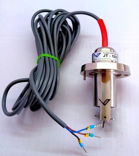
Hall Effect Flow Sensors for Liquid Flow Measurement
Liquid passing through the valve turns a rotor. A hall effect sensor converts the rotor speed into a pulse signal, giving the flow rate. Available in PP and SS valves, including flameproof versions.
Certifications
Key Features
Valve Variants
| Valve | Type | Max. Pressure | Max. Temperature |
|---|---|---|---|
| PP flow sensor | Magnetic | 6 bar | 60°C |
| SS flow sensor | Magnetic | 10 bar | 100°C |
| SS flow sensor | Non-magnetic | 10 bar | 60°C |
| SS flow sensor, flameproof | Magnetic | 10 bar | 100°C |
| SS flow sensor, flameproof | Non-magnetic | 10 bar | 60°C |
Applications
Technical Specifications
Accuracy
±1% of full scale if velocity is more than 0.5 m/s.
Input Voltage
12 to 24 VDC
Output
High frequency pulse, 30 to 70 Hz.
Solids / Impurities
Max. 1% of fluid volume; non-abrasive, non-magnetic, below 100 micron in diameter and length.
Fitting
T type or weld-on adapter fittings for correct mounting in the pipeline.
T Fitting
Provided with the sensor.
How to Choose a Flow Sensor
Use these six steps to specify the right paddle type flow sensor.
1. Check your fluid
Clean, non-abrasive liquid with up to 1% solids, non-magnetic and below 100 micron.
2. Note pressure and temperature
PP valve: 6 bar and 60°C. SS valve: up to 10 bar and 100°C.
3. Pick the valve material
PP or SS, in magnetic or non-magnetic versions, to suit your fluid and temperature.
4. Decide on flameproof
Choose the SS flameproof version where flameproof equipment is required.
5. Match the signal
12 to 24 VDC supply with a 30 to 70 Hz pulse output for your indicator or controller.
6. Select the fitting
T type or weld-on adapter, fitted to your pipeline for best performance.